
Sustaining life on a spacefaring mission presents intense cleantech challenges in efficiency and reuse.
One interesting technology development that started in the Gemini program, with an eye to the needs of the Apollo spacecraft, was the electric fuel cell. This is a vintage Apollo Fuel Cell Power Plant.
The Apollo spacecraft used liquid hydrogen and oxygen for primary power, air, cooling, and water. (The hydrogen and oxygen could have also been used for propulsion in a more parsimonious design.)
The three fuel cell power plants in the Service Module combined hydrogen and oxygen to generate electricity onboard. The waste stream of the fuel cell is pure water, which was used for consumption by the crew.
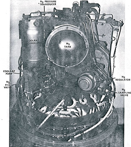
On the inside are 31 individual fuel cells, connected in series, which operate at 27 to 31 volts. Normal power output is 563 to 1420 watts, with a maximum of 2300 watts. Primary construction materials are titanium, stainless steel, and nickel.
This particular fuel cell is Serial Number 1 and was for the simulator. It is identical to the flight unit, but with additional simulator functionality and interfaces.
It is the perfect complement to the Command Module instrument panel that I posted earlier with annotated controls and displays for the fuel cells and related Apollo 13 drama.
I’ll post additional photos and diagrams of this fuel cell below.
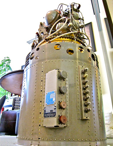 With Electrical and LOX/LOH Connectors at the bottom.
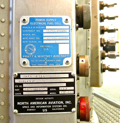 Overview:
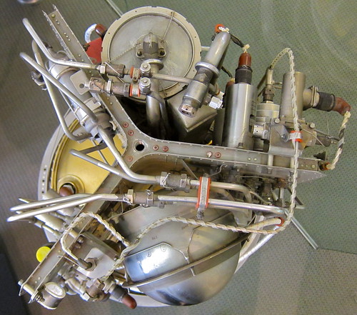 Details:
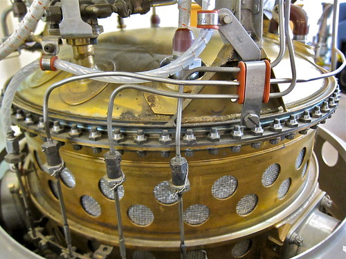
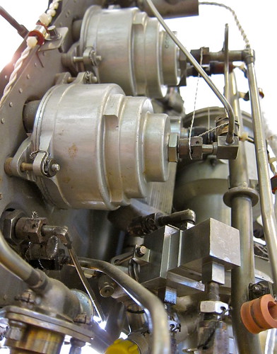
 Reactant Preheaters:
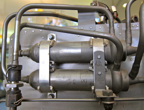 Apollo Fuel Cell Power Plants installed in Command Service Module Bay Sector 4
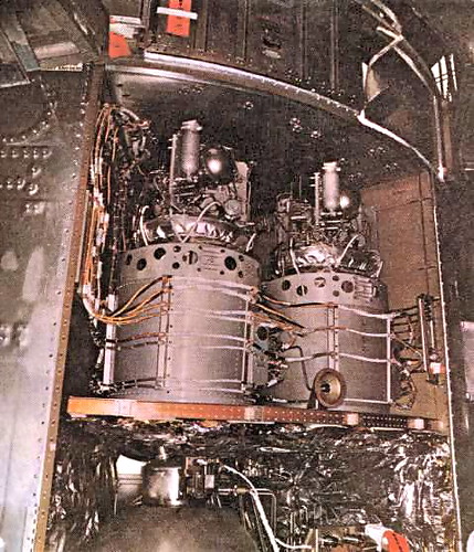 Technical Details from Spaceaholic:
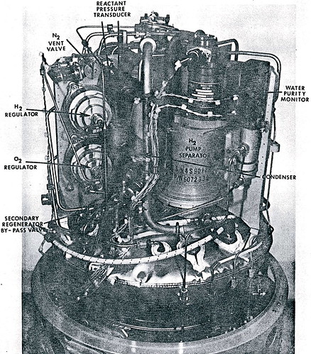


Leave a Reply to JeffSech Cancel reply