Canon PowerShot G9
ƒ/4
7.4 mm
1/60
80

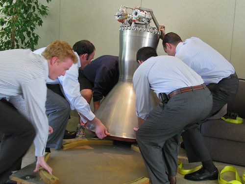
I gasped when I looked out the window and saw this enormous crate at the front door.

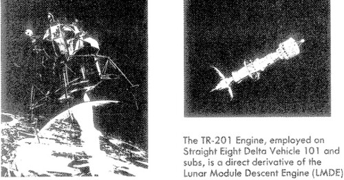
This Apollo era rocket engine was originally designed for the Lunar Module Descent Engine (LMDE or DPS), and then employed as the 2nd-stage engine on the Delta Space Launch Vehicle. This may be the only complete unit in existence.

During the Apollo 13 emergency, the LMDE brought the spacecraft back to earth from the moon in an untested manner. Since an earlier explosion took out the main oxygen tanks, they improvised and used the LMDE— the engine from the lunar lander, designed to slow its decent to the moon — to instead push the crippled Command Module and reentry capsule for the return burn and subsequent course corrections. (Here are some Interesting details from Lovell and Haise)

This engine uses hypergolic fuels – noxious chemicals that combust on contact and make for simple, reliable engines that you can use repeatedly in the vacuum of space. The pump for these fuels on the LM ascent engine was the focal point of Neil Armstrong’s nightmares before the Apollo 11 launch.

I’ll post some unpacking photos and details as I gather them below.

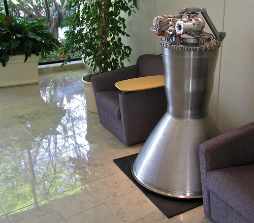
Big thanks to Spaceaholic for the following details, engraved in a plaque that now hangs above it in our lobby:

“TRW TR-201 Bipropellant Rocket Engine. The thrust chamber was initially developed for the Apollo Lunar Module and was subsequently adopted for the Delta Expendable Launch Vehicle 2nd stage. The engine made 10 flights during the Apollo program and 77 during its Delta career between 1974-1988. This TR-201 has been configured as a fixed thrust version of the Lunar Module Descent Engine (LMDE) for Delta’s stage 2. Multi start operation is adjustable up to 55.6 kN and propellant throughput up to 7,711 kg; and the engine can be adapted to optional expansion ratio nozzles. Development of the innovative thrust chamber and pintle design is credited to TRW Aerospace Engineer Dr. Peter Staudhammer.

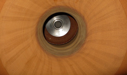
The combustion chamber consists of an ablative-lined titanium alloy case to the 16:1 area ratio. Fabrication of the 6A1-4V alloy titanium case was accomplished by machining the chamber portion and the exit cone portion from forgings and welding them into one unit at the throat centerline. The ablative liner is fabricated in two segments and installed from either end. The shape of the nozzle extension (not installed on the example in this collection) is such that the ablative liner is retained in the exit cone during transportation, launch and boost. During engine firing, thrust loads force the exit cone liner against the case. The titanium head end assembly which contains the Pintle Injector and propellant valve subcomponents is attached with thirty-six A-286 steel ¼ inch bolts.

In order to keep the maximum operating temperatures of the titanium case in the vicinity of 800 degrees (F), the ablative liner was designed as a composite material providing the maximum heat sink and minimum weight. The selected configuration consisted of a high density, erosion-resistant silica cloth/phenolic material surrounded by a lightweight needle-felted silica mat/phenolic insulation.

The installed Pintle Injector, unique to TRW designed liquid propulsion systems, provides improved reliability and less costly method of fuel oxidizer impingement in the thrust chamber then conventional coaxial distributed-element injectors typically used on liquid bipropellant rocket engines.

Number flown: 77 (Delta 2000 configuration)
Dry mass: 300 pounds (with Columbian Nozzle Extension Installed)
Length: 51 inches – Gimbal attachment to nozzle tip (minus nozzle extension)
Maximum diameter: 34 inches (minus nozzle extension)
Mounting: gimbal attachment above injector
Engine cycle: pressure fed (15.5 atm reservoir)
Fuel: 50/50 N2O4/UDMH at 8.92 kg/s
Oxidizer: Dinitrogen tetroxide at 5.62 kg/s
O/F ratio: 1.60
Thrust: 42.923 kN vac
Specific impulse: 303 s vacuum
Expansion ratio: 16:1, 43:1 (with Expansion Nozzle)
Cooling method: Film cooled (upper thrust chamber); quartz phenolic chamber ablation (lower thrust chamber) and columbium (niobium) nozzle radiation (Nozzle extension)
Chamber pressure: 7.1 atm
Ignition: hypergolic, started by 28 V electrical signal to on/off solenoid valves
Burn time: 500 s for total of 5 starts; 10 350 s single burn”

24 responses to “The Eagle has Landed”

  1. Here is the opening image from a 1976 TRW document on the engine:

    Delta 1976 Brochure

    Loading into position:
    Unloading IMG_0046

    And in place:
     In place IMG_0056

    I have a cool display plan – it will be on top of a circular matching wood table of the same outer radius, but with a glass center. This will allow for a tilted mirror to give a peek up the skirt…. =)

    …which I had to do on arrival, and this is what I saw:
    Up Skirt IMG_0054

    Interior Nozzle View – Pintle Injector. The ring of dots in the center are annular ports which drizzled propellant down the upper thrust chamber walls for film cooling.

    Location in our lobby, as seen from the front door:
    Lobby IMG_0060

  2. always such awesome goodies.

  3. Whhahaaaaaaat!?!?!?

    Now I’ve gotta come up with an excuse to come visit!

  4. Piece by piece… steve is secretly assembling his return rocket. Now THAT’s a lobby stopper. 😉

  5. Heh… astronaut farmer in suburbia…

    And some other interesting perspectives…

    TR-201 Briefing

    TR-201 Headend And Injector Flow:
    TR-201 Headend And Injector Flow

  6. Any chance of a tour, Steve?

  7. Holy cow! What a desk ornament!

  8. Definitely an interesting conversation piece, but even this I fear will not help your descent to earth. I think you are truly not of this world! This is definitely going to make me take a second look at our waiting room!

  9. Nice office decoration – it will be a conversation starter.

  10. Someone please photoshop SJ’s head on Werrner Von Braun’s body in this photo: blog.untitledfornow.com/wp-content/uploads/2009/07/S-IC_e…

    PS: a Saturn five nozzle would make A NICE OFFICE.

    PPS: pray tell, where did you score the LDME…that has to be good story!

  11. Too funny! Steve Von Jurvebraun.

  12. Years ago, probably about the time this engine was being made, there was only one source in the US for UDMH. And that company had decided to stop making it when it became known that UDMH was a carcinogen…. the company also had major branches working in the food industry and couldn’t be tainted with the carcinogen label. The whole episode led to some very long delays in launching some Titan SLVs, and almost the cancellation of the Mars Mariner 8&9 missions. So… your mission, should you decide to take it, is to find an environ friendly substitute for UDMH. I’m not too sure about MMH, but I don’t think I would keep any of that in my garage either. 😉

    Congrats on the acquisition- a neat find! Good to see some of this history being preserved.

    PS I’m not a chemist, but I’m pretty sure that MMH is not an oxidizer (there’s no O in it). I think N2O4, IRFNA or LOX was used for the oxidizer. MMH was frequently mixed with the UDMH as the fuel. I think that some impish transmutation occurred in the engine description above.

  13. Steve, it will look great on the table you described. It is a wonderful purchase, albeit certainly expensive.

    At least you can boast that you are starting a mini space museum to conserve items from history. That would be a good idea if you purposefully set on this road. All you need is a few more items to your growing collection. Perhaps also contributions from your friends and clients. Make it official and plan the Jurvetson Space Museum.

    Others might think about impressing your office visitors but I am thinking of your children who have some of the the most unusual items to show off when they talk about their father’s office! How cool is that for them to have such an out-of-the-ordinary dad!

    Congratulations on this purchase and may there be many more!

  14. Good ideas Mimosa! Starting with a more modest scale, but who knows… The strategy is acquire artifacts too heavy for the partners to move, and then rely on creeping incrementalism and inertia and voilà!

    rdavidschwartz : Love the Zelig-shop…. glad I wasn’t wearing the dress

    Jerryfi_99: good point. From this site, the propellants were N2O4 and Aerozine-50 . Looks like the MMH was mixed with the hydrazine in some cases. The N2O4 is clearly the oxidizer, so yes, they got the propellants jumbled a bit. Here is a good overview. I will edit the oxidizer line of the table.

    P.S. Here is another historical image of the injector assembly without the mounting struts:

    TR201 Injector

    You can see the bipropellant butterfly valve assembly on the left. From rocket relics:

    "Bi-Propellant Rocket Engine Tandem Actuator Valve Assembly which regulated the flow of Propellants (both fuel and oxidizer) into the thrust chambers Pintle injector.

    tr201_actuator

    The two simple on-off butterfly type propellant vales are actuated in tandem on command by a single hydraulic actuator.

    The major components of the actuator are the solenoid valve assembly and the hydraulic cylinder. The redundant coil solenoid is designed such that either coil is fully capable of operating the actuator in the event of electrical failure of one of the coils. To insure that the actuator remains closed without availability of supply pressure, a simple mechanical fingerlock is built in the hydraulic cylinder. The fingerlock engages the internal cam in the piston when the actuator is closed and disengages when the solenoid assembly applies supply pressure to open the actuator. The piston lock is spring loaded to return between the fingers when the actuator is retracted.

    The internal seal of the propellant shutoff valve is a a highly reliable design compatible with both propellants (the TR-201 employed a hypergolic combination of nitrogen tetroxide and aerozine-50 operating at a 1.6 mixture ratio). The seat design consists of two parts: a Teflon seal ring and an elastomer backing o-ring. The I.D. surface of the seal ring serves to effect a seal against the valve disc while its flange area securely locks the ring into a machined “T” slot within the valve body. When the disc is in the closed position, the backing ring preloads the seal ring against the disc affording a static seal. Propellant pressure along with the “T” slot creates a piston action of the seal ring amplifying the sealing force. The seal tightens as propellant pressure increased. "

    tr201_actuator_diagram

  15. One more request, please, before I leave your photostream for this evening: Eye for Science?

  16. Holy cow…my long lost twin brother…sign me up.

  17. Steve you have to watch this !!!
    Reminded me of of you with the space toys, and this photo =)
    Neil deGrasse Tyson Opens A Rocket In His Office


    "This video just goes to show that boys never really grow up, but their toys sure do."

    =) So you !

  18. a friend forwarded me this description from an Apollo S-IVB engine engineer, with the amazing part in bold added:

    "I worked as a Design Engineer on this engine starting in January 1963 at a TRW facility located in Inglewood Calif. We had a total team of about 3 designers – Draftsman and 3 engineers along with our support staff of (2) machinist and office support. We had our own machine shop that made the prototype parts including the injector heads, throats, and thrust chambers and nozzles. A test firing range was located a few miles from the engineering location. When we starting a test firing schedule we would stay on at the site to complete the mission profile but we destroyed a number of engineers trying to perfect a design that worked.

    We must have tried over at 25 different designs and refrasil material changes for both the combustion chambers and metal throat and nozzles. I worked a normal 60 – 70 hours a week for about 1 ½ Years. No computers on CAD equipment in those days just trial and error. Another interesting point we made total engines out clear Plexiglas (not the Injector Heads) and set them up and mounted with high speed camera to view the fuel flow into the chamber and witness the explosion before the material melted!

    The production engines were manufacturing in Euclid Ohio at a production plant that TRW had. I was not only involved in the design phase but also went to Ohio to support the production build schedule of about 100 engines."

  19. Reposting some content hidden behind the "More" link: Here is the opening image from a 1976 TRW document on the engine:

    Delta 1976 Brochure

    Loading into position:
    Unloading IMG_0046

    And in place:
     In place IMG_0056

    I have a cool display plan – it will be on top of a circular matching wood table of the same outer radius, but with a glass center. This will allow for a tilted mirror to give a peek up the skirt…. =)

    …which I had to do on arrival, and this is what I saw:
    Up Skirt IMG_0054

    Interior Nozzle View – Pintle Injector. The ring of dots in the center are annular ports which drizzled propellant down the upper thrust chamber walls for film cooling.

    Location in our lobby, as seen from the front door:
    Lobby IMG_0060
    And some other interesting perspectives…

    TR-201 Briefing

    TR-201 Headend And Injector Flow:
    TR-201 Headend And Injector Flow

Leave a Reply to Victor1 Cancel reply

Your email address will not be published. Required fields are marked *